>
Packing
List:
Box
#1:
Frame/engine
assembly
Rear brake rod
Seat cover
Upturned pipe (optional)
Ape Hangar bars (optional)
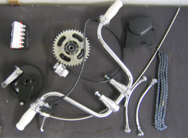
Box
#2:
Front wheel
assembly
Rear wheel
assembly
Rear brake
hub
Rear wheel
sprocket hub
Handlebar
assembly with front brake
Chain
Chain cover
Battery
Rear fender
brace tube assemblies (L&R)
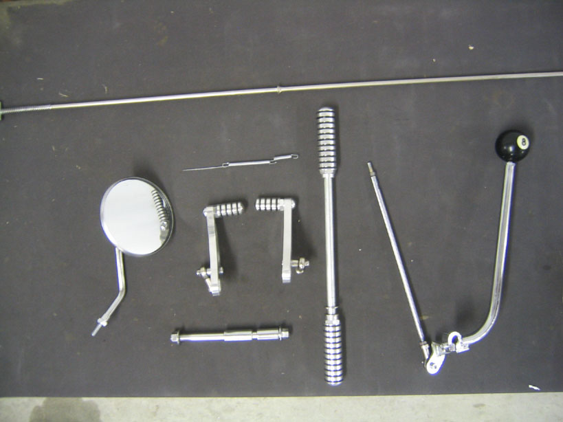
Box
#3:
Front fork
assembly
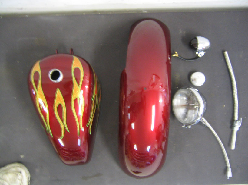
Gas tank
Rear fender
Headlight
Tail light
Gas cap
Fuel line &
petcock
Front axle
(spacers & nut included)
Left and
right foot control
Jockey shift
(pushrod installed)
Forward foot
peg assembly
Rear view
mirror
Brake return
spring
Brake light actuator spring
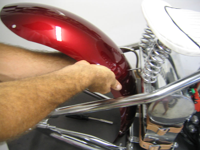
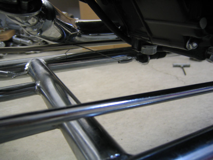
Place frame assembly on stand
Install
rear fender using
the two attach bolts in the center of the frame.
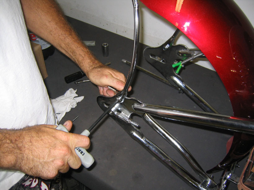
Install
rear fender brace tubes. Note that the fork end of
the brace tubes tubes attach to the frame. The
left side bracket has the tail light attachment.
Place chain
on engine drive sprocket.
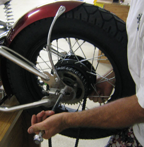
Place the brake and sprocket hubs on the rear wheel.
Align the rear wheel assembly with rear axle plates on
frame. Place chain on wheel sprocket. Put rear axle
through chain adjuster on frame, axle spacers, and rear
wheel assembly. Note: The longer axle spacer goes on the
brake side. Ensure correct chain tension by using chain
adjusters on frame. Tighten axle nut*.
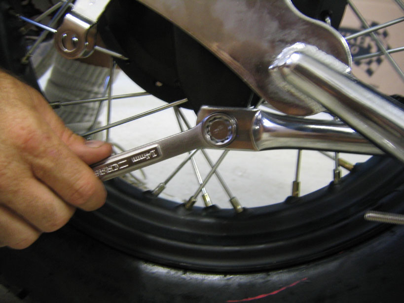
Install
brake hub brace tube. Check to make sure tire does
not make contact with rear fender brace tube bolts.
Hub attach point should be at the 6 oclock position.
Install
chain guard on engine.
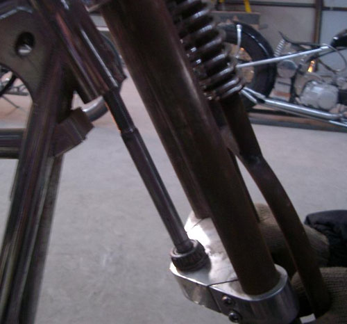
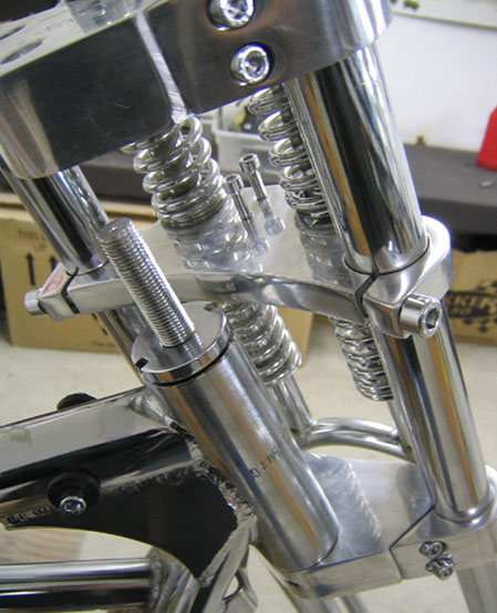
Tighten
upper triple clamp on fork tubes. Triple clamp should be
flush with the top of the fork tubes. Loosen lower
triple clamp and
slide down fork. Place flat washer on
steering bolt.
Apply
high temperature bearing grease to tapered steering
bearings. Place one bearing on steering bolt above the
washer and install the second on the top race on frame
steering tube. Slide steering bolt up through steering
tube .
Hand tighten threaded washer on large bolt under
upper triple clamp. Slide upper triple clamp down over
steering bolt. Install and tighten large cap nut on top
of upper triple clamp*. Tighten lower triple clamp* on
fork tube.
Loosen
springer clamp and position midway between high and low
travel.
Retighten
clamp onto fork tubes*.
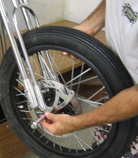
Install
front wheel by placing front axle through lower
rockers and wheel spacers. The shorter spacer goes on
the rotor side of the wheel. Tighten axle nut*.
Place fiber/metal washer on exhaust port and
bolt exhaust to engine head. Place rubber fender washer
between exhaust mounting tang and frame and attach bolt.
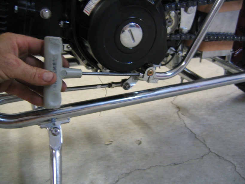
Install kick
starter pedal on splined shaft. Tighten both clamp bolt
and set screw*.
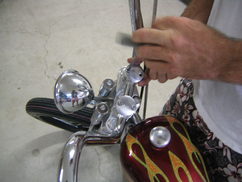
Secure
headlight to springer clamp*. Connect headlight wire to
plug on frame.
Install
handlebar risers on upper triple clamp. Make sure
that risers are aligned to fit the handlebar before
tightening.
Place
handlebar on risers and secure in place with riser
caps*.
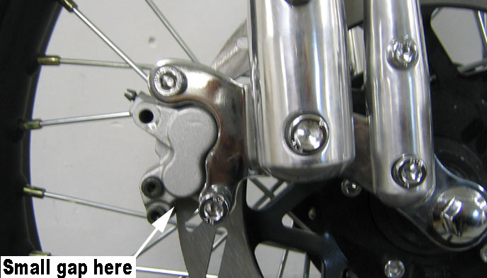
Remove
plastic chock between the pads on the brake caliper.
Slide caliper onto rotor and
Attach front brake caliper to mounting bracket. If
caliper bolt holes do not align with the bracket holes,
slide springer clamp up or down. This will reposition
the brake rotor and allow the caliper bolt holes to
align. If needed the triple clamps can be loosened to
rotate the fork tube to align the caliper bracket with
the rotor. Once the caliper is bolted to the bracket,
lower the springer clamp on the fork until the brake
caliper is close but not touching the outer edge of the
rotor. Retighten springer clamp and the triple clamp
bolts*.
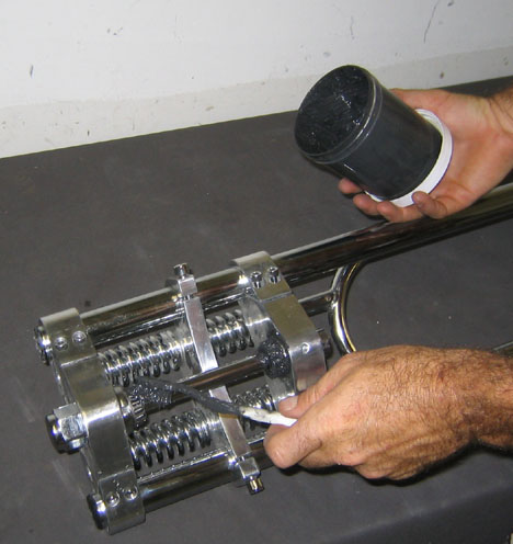
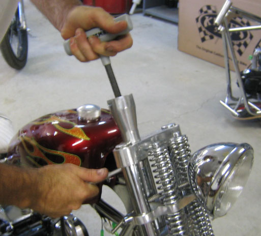
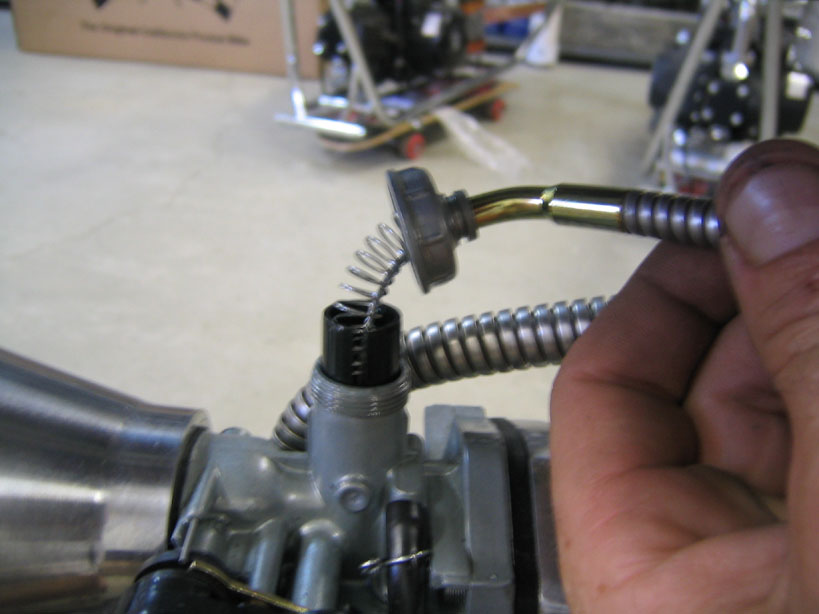
Unscrew the
top of the carburetor and remove slide. Warning: The
slide return spring is under tension and may exit the
vehicle. To remove the slide place your pinky finger
inside the top of the carb down to the slide. Hold side
pressure on the slide and pull up. Feed
the throttle cable through the carb top and return
spring. Secure the end of the throttle cable to the slot
on the slide. Place the slide into the carb making sure
that the beveled edge of the slide is towards the air
filter. Hand
tighten
the top of the carb. If it is necessary to
adjust the throttle housing on the handlebar
you must first loosen the housing set screw . Be aware
that the two screws that hold the housing halves
together are only to be snug tight and do not fixate the
housing on the bar. If these screws are overtightened
the threads may strip and this will not be covered under
the warranty.
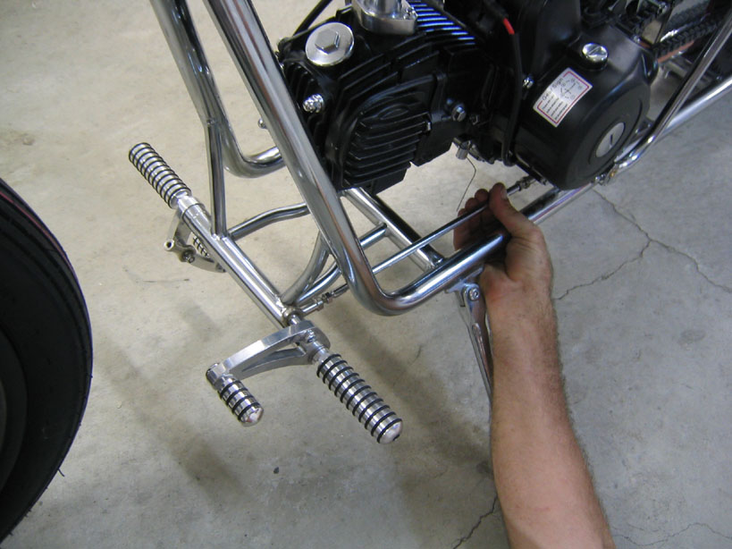
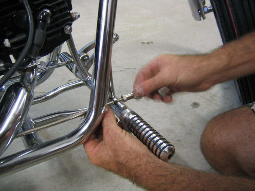
Place
forward control horns onto brass bushings and
position into forward foot peg mount on frame. Note that
the top of the control horn is convex.
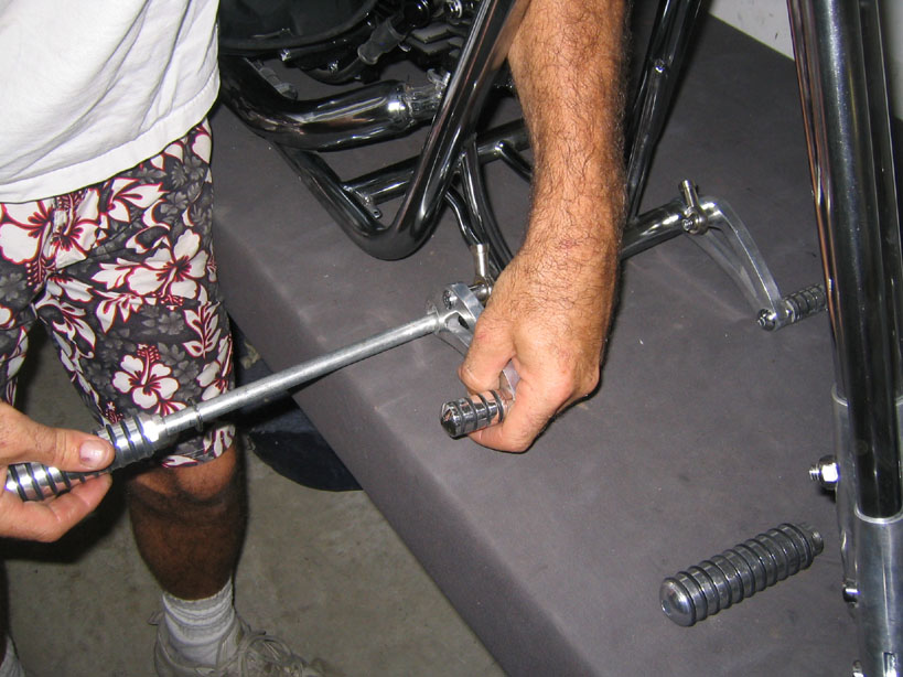
Slide
threaded foot peg rod through frame tube and place
flat washers against each control horn. Screw foot pegs
onto threaded rod*. Do not overtighten as this will
fracture brass bushings. Check to see that the control
horns rotate freely. If not you may need to dress
the brass bushings with a file to give free clearance.
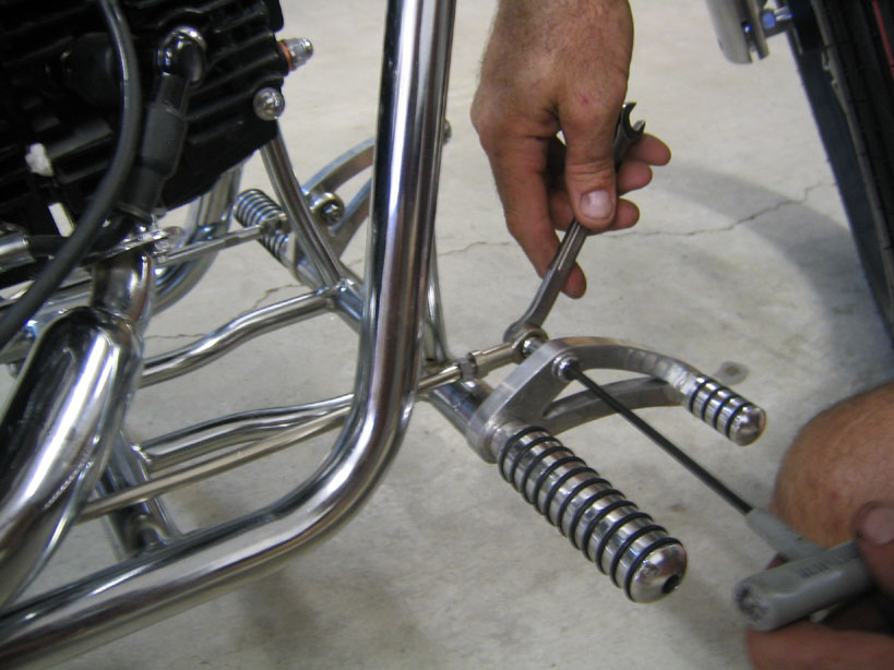
Remove rod
end from left control horn and thread onto jockey shift
pushrod.
Reinstall
rod end onto control horn.
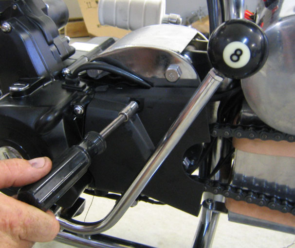
Slide
jockey shift onto gearshift spline on engine and
tighten clamp bolt*.
Place
tail light on mounting bracket on left rear fender
mount tube and secure with bolt. Plug wires into
corresponding wires inside faux oil tank which can be
accessed by removing the left side cover.
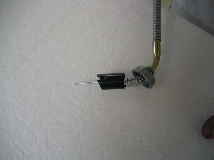
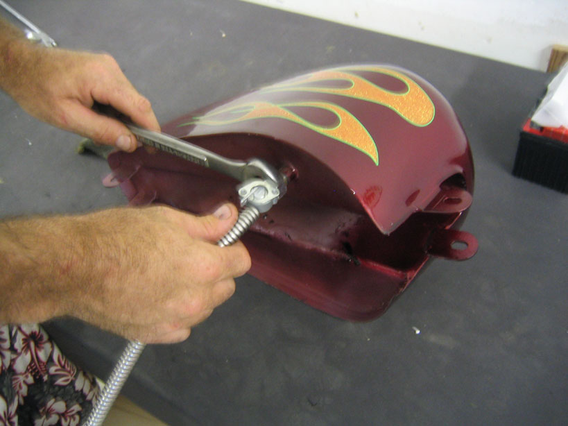
Apply pipe
sealant and
Thread
petcock onto gas tank fitting. Make sure that the
lever is to the right side of the tank.
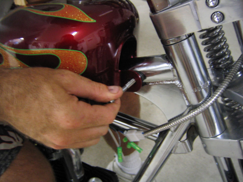
Place gas
tank onto frame and place rubber washers under brackets.
Install
mounting bolts. With the stainless steel cover over
the fuel line, push fuel line onto tank petcock and
carburetor. Thread gas cap onto filler neck.
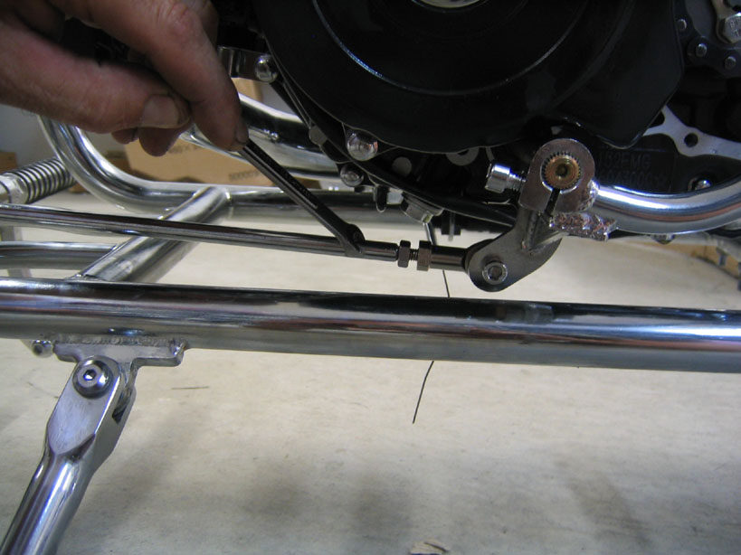
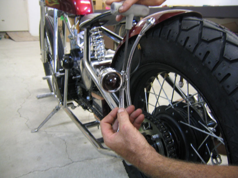
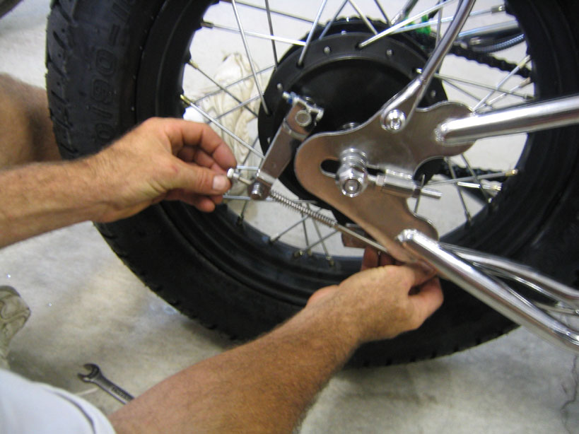
Remove
adjustment nut, barrel and spring from rear brake rod.
Make a slight bend 8 from the rear end and 4 from the
front on the rod. Reinstall spring. Put brake barrel
through brake arm on wheel hub. Place rear brake rod
through alignment bracket on frame and brake barrel.
Thread
adjustment nut onto brake rod. Note that the brake
arm should be at the
7 Oclock position if
properly adjusted. If not, the brake arm can be
repositioned on the splined shaft.
Remove
rod end from right control horn. Thread rod end onto
brake rod.
Reinstall
rod end onto control horn.
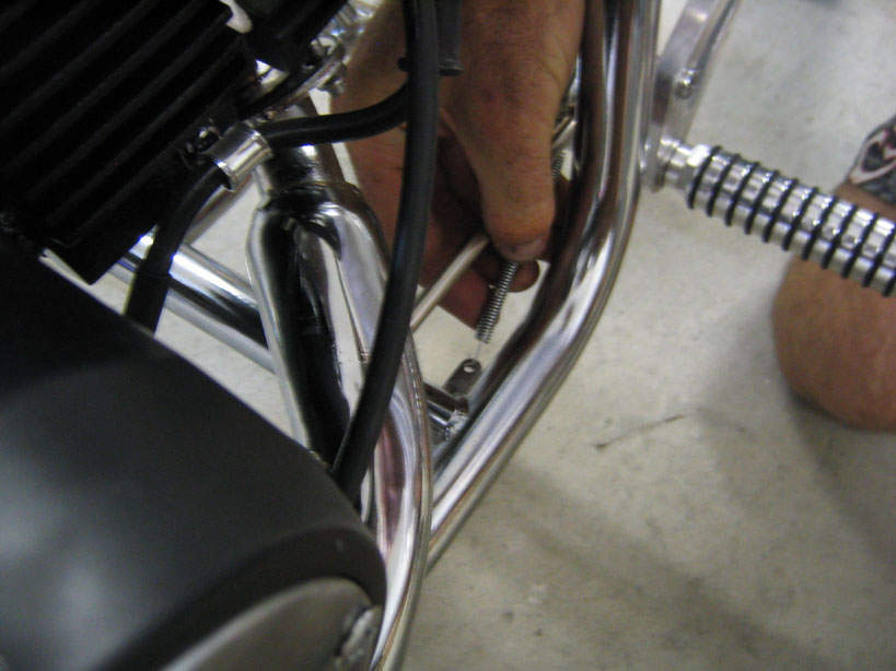
Install
brake rod return spring between frame tang and hole
drilled through brake rod.
Install
brake light actuator spring to switch on the frame
under the kick start pedal. Slide strait spring end
through hole in brake rod end and bend back.
Install rear
view mirror.
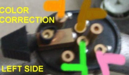
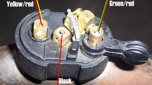
Connect left side switch to wires on handlebar.
Connect right side switch to wires on handlebar.
Connect red
(positive) and black (negative) wires to battery. Secure
battery with rubber blocks. replace battery box side
cover and tighten leather straps. Note: electric start
will not function unless rear brake is depressed.
Check engine oil level. Use 20w50 motor oil.
Recheck
tightness of all bolts and nuts on bike. Be sure that
the set screws on the side covers of the electrical box
are tight and have Loctite applied.
Inflate tires to
32 psi.
*Apply Loctite thread lock on threads.
.